Acquisition & Contrôle | conditionneurs de signaux | i420

i420 Product Overview
The i420 card plugs into a 4 to 16 slot instruNet i4xx Card Cage, which in turn attaches to a Windows computer
This Amplifier (not A/D) module provides 20se/10di voltage input channels (Ch#1...#20)40 , each of which are independently software programmable with Windows software that support the direct connection to many common sensor types
This module does not contain an A/D converter, and therefore internally routes measured voltage to an i43x A/D module anywhere in card cage. At least one i43x must be installed in order to measure a voltage with this module.
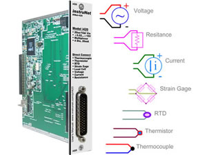
Each of the 10 differential channels support the direct connection to the following sensor types (click for Wiring Diagram and Setup Instructions): Voltage, Thermocouple, Thermistor, RTD, Load Cell, Strain Gage, Potentiometer, Current, Resistance
Voltage input range on each channel is independently software programmable to one of: ±20mV, ±40mV, ±80mV, ±2.5V, ±5V, ±10V, 0 to 5V, 0 to 10V
Each channel provides the following software programmable parameters: A/D Signal-Averaging-Per-Point (0 ... 100mSec)3 , Sample-Rate (samples-per-second-per-channel)17 , Digital IIR Filter (LowPass, HighPass, BandPass, or BandStop)55 , Voltage Measurement Range (±20mV...±10V)1 , Sensor Type13 , and Single-Ended or Differential Wiring
Each channel provides optional digital IIR lowpass, highpass, bandpass and bandstop filters with independent software programmable cut-off frequency, minimum dB stopband attenuation, maximum dB passband attenuation, and filter type (e.g. Elliptic, Chebyshev B, Chebyshev S, and Butterworth). Number of poles/zeros (i.e. "filter order") is programmable between 2 and 32e55 .
Excitation power (+3.3V ±.2V, <0.22A, 22mA per sensor max) is provided for sensors, along with other End User Power voltages. This 3.3V, which is referenced to instruNet Ground, is automatically readback by A/D when calculating sensor values.
The 20mA sink digital I/O port consists of 4 individual TTL-compatible lines (Ch#25...#28), each of which can be configured as: digital input bit, digital output bit, control output, clock output43 . When configured as an input, a channel can be used to sense a digital high (2.1 to 30 Volts) or digital low (-10V to .65Volts). When configured as an output, a channel can be set high (e.g. >2V) or low (e.g. <0.8V). These I/O pins are short-circuit protected against high voltages up to 32.0V and down to -16.0V.
Spécifications:
# of Analog Inputs
20se / 10di
Range selection
Each individually programmable
Input ranges
+/-20mv to +/- 10 Volts
Sensor type
Voltage,thermocouple,thermistor,RTD,Load Cell,Strain Gage,Potentiometer,Current,Resistance
Filter (optional)
LP,HP,BP, Stopband
Digital I/O
4 Bi-directionnal, 20ma sink
Nous tenons à ce que votre expérience de navigation sur note site soit agréable & productive. Pour toute question technique, nos représentants se feront un plaisir de vous guider pour un choix éclairé et approprié à vos besoins.
En visitant notre site, indiquez les produits qui suscitent votre intérêt en cliquant sur ajouter à mes interêts.
Besoin d'une solution ?
Nous pouvons vous apporter la réponse !