Acquisition & Control on PC | Uinversal Sensor Input | i420

Detailed features:
i420 Product Overview
The i420 card plugs into a 4 to 16 slot instruNet i4xx Card Cage, which in turn attaches to a Windows computer
This Amplifier (not A/D) module provides 20se/10di voltage input channels (Ch#1...#20)40 , each of which are independently software programmable with Windows software that support the direct connection to many common sensor types
This module does not contain an A/D converter, and therefore internally routes measured voltage to an i43x A/D module anywhere in card cage. At least one i43x must be installed in order to measure a voltage with this module.
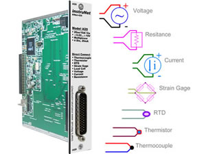
Each of the 10 differential channels support the direct connection to the following sensor types (click for Wiring Diagram and Setup Instructions): Voltage, Thermocouple, Thermistor, RTD, Load Cell, Strain Gage, Potentiometer, Current, Resistance
Voltage input range on each channel is independently software programmable to one of: ±20mV, ±40mV, ±80mV, ±2.5V, ±5V, ±10V, 0 to 5V, 0 to 10V
Each channel provides the following software programmable parameters: A/D Signal-Averaging-Per-Point (0 ... 100mSec)3 , Sample-Rate (samples-per-second-per-channel)17 , Digital IIR Filter (LowPass, HighPass, BandPass, or BandStop)55 , Voltage Measurement Range (±20mV...±10V)1 , Sensor Type13 , and Single-Ended or Differential Wiring
Each channel provides optional digital IIR lowpass, highpass, bandpass and bandstop filters with independent software programmable cut-off frequency, minimum dB stopband attenuation, maximum dB passband attenuation, and filter type (e.g. Elliptic, Chebyshev B, Chebyshev S, and Butterworth). Number of poles/zeros (i.e. "filter order") is programmable between 2 and 32e55 .
Excitation power (+3.3V ±.2V, <0.22A, 22mA per sensor max) is provided for sensors, along with other End User Power voltages. This 3.3V, which is referenced to instruNet Ground, is automatically readback by A/D when calculating sensor values.
The 20mA sink digital I/O port consists of 4 individual TTL-compatible lines (Ch#25...#28), each of which can be configured as: digital input bit, digital output bit, control output, clock output43 . When configured as an input, a channel can be used to sense a digital high (2.1 to 30 Volts) or digital low (-10V to .65Volts). When configured as an output, a channel can be set high (e.g. >2V) or low (e.g. <0.8V). These I/O pins are short-circuit protected against high voltages up to 32.0V and down to -16.0V.
i420 Product Overview
The i420 card plugs into a 4 to 16 slot instruNet i4xx Card Cage, which in turn attaches to a Windows computer
This Amplifier (not A/D) module provides 20se/10di voltage input channels (Ch#1...#20)40 , each of which are independently software programmable with Windows software that support the direct connection to many common sensor types
This module does not contain an A/D converter, and therefore internally routes measured voltage to an i43x A/D module anywhere in card cage. At least one i43x must be installed in order to measure a voltage with this module.
Each of the 10 differential channels support the direct connection to the following sensor types (click for Wiring Diagram and Setup Instructions): Voltage, Thermocouple, Thermistor, RTD, Load Cell, Strain Gage, Potentiometer, Current, Resistance
Voltage input range on each channel is independently software programmable to one of: ±20mV, ±40mV, ±80mV, ±2.5V, ±5V, ±10V, 0 to 5V, 0 to 10V
Each channel provides the following software programmable parameters: A/D Signal-Averaging-Per-Point (0 ... 100mSec)3 , Sample-Rate (samples-per-second-per-channel)17 , Digital IIR Filter (LowPass, HighPass, BandPass, or BandStop)55 , Voltage Measurement Range (±20mV...±10V)1 , Sensor Type13 , and Single-Ended or Differential Wiring
Each channel provides optional digital IIR lowpass, highpass, bandpass and bandstop filters with independent software programmable cut-off frequency, minimum dB stopband attenuation, maximum dB passband attenuation, and filter type (e.g. Elliptic, Chebyshev B, Chebyshev S, and Butterworth). Number of poles/zeros (i.e. "filter order") is programmable between 2 and 32e55 .
Excitation power (+3.3V ±.2V, <0.22A, 22mA per sensor max) is provided for sensors, along with other End User Power voltages. This 3.3V, which is referenced to instruNet Ground, is automatically readback by A/D when calculating sensor values.
The 20mA sink digital I/O port consists of 4 individual TTL-compatible lines (Ch#25...#28), each of which can be configured as: digital input bit, digital output bit, control output, clock output43 . When configured as an input, a channel can be used to sense a digital high (2.1 to 30 Volts) or digital low (-10V to .65Volts). When configured as an output, a channel can be set high (e.g. >2V) or low (e.g. <0.8V). These I/O pins are short-circuit protected against high voltages up to 32.0V and down to -16.0V.
Specifications:
# of Analog Inputs
20se / 10di
Range selection
Each individually programmable
Input ranges
+/-20mv to +/- 10 Volts
Sensor type
Voltage,thermocouple,thermistor,RTD,Load Cell,Strain Gage,Potentiometer,Current,Resistance
Filter (optional)
LP,HP,BP, Stopband
Digital I/O
4 Bi-directionnal, 20ma sink
My Interests
This is our way of making your browsing experience a success. If you have any technical questions, we will make it our pleasure to review this list and find the solution that's right for you.
While browsing, add the products you are interested in by clicking on the add to my interest buttons.
More ways to order
Need Solutions?
We can provide the answer!